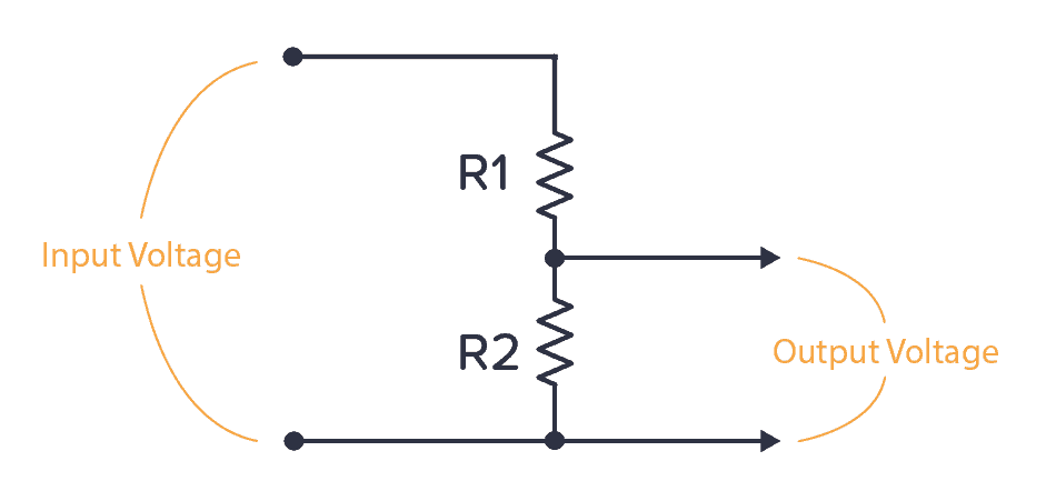
A voltage divider a basic circuit creates an output voltage that is a fraction of the input voltage. It includes two resistors linked in series with the output voltage sourced from the connection between them.

However factors like resistor tolerances and measurement inaccuracies can lead to actual output voltage differing from the theoretically calculated value. By determining the error of a voltage divider we can measure this deviation and grasp its consequences.
Voltage Dividers
Voltage dividers are essential components within electrical circuits as they proportionally decrease voltage serving crucial roles in electronics. They provides a practical method to attain a desired voltage output from a higher voltage source catering to a wide array of applications and ensuring efficient voltage control.
Understanding Voltage Divider Error
Voltage divider error plays out like an enigmatic puzzle where the expected outcome seldom mirrors the intricate reality within a voltage divider circuit. This discrepancy unfolds due to a myriad of factors inherent in component traits and circuit layouts.
Factors Influencing Error
When analyzing a voltage divider circuit it becomes apparent that component tolerances temperature fluctuations and loading effects all play significant roles in influencing the overall error within the system.
Calculation Formula
The calculation of the voltage dividers error encompasses a distinctive formula that takes into account the individual resistors tolerances within the circuit.
The output voltage (Vout) of a voltage divider can be calculated using the formula:
Vout = V in X R2 / R1+ R2
Where:
- V in is the input voltage.
- R1 and R2 are the resistances of the two resistors in the divider
Ideal vs. Real Voltage Divider
Ideal Voltage Divider
In an ideal world imagine a voltage divider circuit as a skilled performer smoothly converting input voltage into output voltage flawlessly executing its task. However the real world introduces its unique twists disrupting this seamless operation.
Real-World Factors Impacting Accuracy
Resistor discrepancies variations in temperature and the diverse range of external loads intricately impact the precision of voltage dividers consequently introducing discrepancies into the output voltage measurements.
Calculating Error in Voltage Divider
When evaluating the precision of a voltage divider embracing a systematic approach that contemplates component tolerances and correlating factors emerges as indispensable.
Step-by-Step Method
- Investigate the nominal values and permissible tolerances of the resistors employed in the voltage divider arrangement.
- Calculate the total tolerance of the divider circuit based on the individual resistor tolerances.
- Determine the maximum and minimum possible output voltages considering the tolerance range.
- Let's calculate the error percentage with this straightforward equation:
Error (%) = [(Maximum Value Minimum Value) / Nominal Output Value] x 100%
Techniques for Reducing Mistakes
To guarantee precise voltage measurements and dependable circuit operation minimizing voltage divider error emerges as a critical undertaking. Implementing various strategies becomes essential to mitigate inaccuracies and pave the way for seamless functionality.
- Careful component selection with tight tolerances
- Temperature compensation techniques
- Proper circuit layout and design considerations
- Calibration and adjustment procedures
Applications of Voltage Dividers
Voltage Dividers Utilized Across Diverse Industries
- Sensor interfacing
- Power supply regulation
- Signal conditioning
- Measurement instrumentation
Conclusion
Designing accurate and reliable electronic circuits hinges on mastering the art of calculating a voltage dividers error. Engineers optimize voltage divider circuit performance by factoring in component tolerances and circuit design to minimize errors effectively.
You Might Also Like: How Do You Calculate Parallel Resistors?


